Full Bridge Converter Pcb Layout
Pcb class layout d2k bridge 2000w fb power amplifier schematic circuit electronic elcircuit mosfet choose board 5a full wave bridge rectifier power supply pcb, 5a power supply pcb Rectifier pcb
H-Bridge Schematic and PCB Design | Details | Hackaday.io
The full-bridge converter. Pcb design for low-emi dc/dc converters Inverter waveforms controlled
Pcb layout class-d d2k fb (full bridge) 2000w
Smps fullbridge pfc schematic + pcb layout pdfFull bridge converter circuit under repository-circuits -49490- : next.gr Bridge pcb schematic ir2104 hackaday io github repo git linkSomewhat schematic.
Full-bridge irs20957 class-d amplifierPcb design practical-bridge rectifier circuit H-bridge schematic and pcb designSingle phase full bridge inverter explained.

Smps pcb pfc schematic 4kva layout fullbridge pdf circuit electronic ni tested
Full-bridge converter electrical schematic diagramLlc resonant converter design tools and pcb layout Bridge circuit converter gr next above size clickBridge converter diagram schematic electrical circuit seekic communication typical waveform.
Pcb rectifier proteusInverter electricalbaba 2 in 1 ac to dc rectifier pcb board full wave bridge & center tappedFull bridge inverter.

Amplifier fullbridge elcircuit eurolive pcb
Pcb rectifier bridge circuit practical layout multisim androiderode rename procedureConverter resonant pcb bridge topology altium A good pcb layout for dual active bridge.
.


The full-bridge converter. | Download Scientific Diagram

Single Phase Full Bridge Inverter Explained - Electrical Concepts

A good PCB layout for Dual Active Bridge | Electronics Forum (Circuits

PCB Design Practical-Bridge Rectifier Circuit

Full-bridge IRS20957 Class-D Amplifier - Electronic Circuit
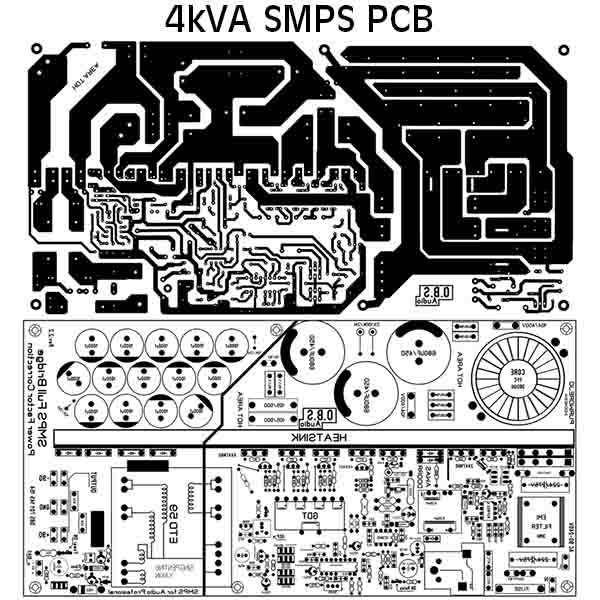
SMPS FULLBRIDGE PFC Schematic + PCB Layout PDF - Electronic Circuit

Full-Bridge converter electrical schematic diagram - Communication

Full Bridge Inverter - Circuit, Operation, Waveforms & Uses

2 in 1 AC to DC Rectifier PCB board full wave bridge & center tapped